
Important notice: This post is about the legacy Nabto 4/Micro platform which has been superseded by the Nabto 5/Edge platform. Also see the general comparison of Nabto 4/Micro (uNabto) and Nabto 5/Edge.
Breaking news!
The CoffeePi will be appearing at Smart IoT London 2016!
Feel free to drop by our booth and get a hot beverage from the CoffeePi served using Nabto!
Back to the story
Please read Part 1 to read about the preliminary steps in the coffee saga.
This part will be dealing with the following points
- Figuring out how to wire up and emulate the rotary knob
- Adding the Nabto framework
- Making the full menu available
- Order a cup of coffee in London, trigger instant brewing in Denmark
The rotary knob
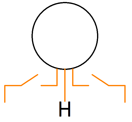
The rotary knob has three pins as seen in the image below
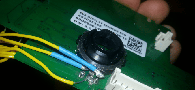
The center pin is common high and the outer pins output the necessary encoder pulse needed for the main board. To get an idea of how these pulses look we checked it out using a logic tester
which gave an output like this
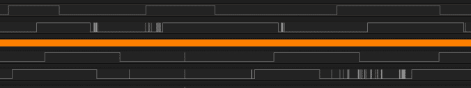
The upper section, in the image above, shows the output from the rotary knob when turning the knob counterclockwise which if equivalent to going left on the main board display. Likewise the bottom section shows the clockwise rotation which result in a right movement on the main board display.
From this we see that the direction the knob is turned can be directly translated into which direction we are moving on the main board display simply by relating which pins changes state first. In other words, to move left/right we need to emulate an output like the top/bottom one seen in the image above.
Before doing that, we need a common starting point, meaning that we need to know if the pins are high or low to begin with. The simplest way to control this was to cut the pins like this
The two switches represent two optocouplers. This means that we can disable the manual rotary knob controls by switching a pin on our Raspberry Pi. Doing that results in the receiving end of the pins to be pulled low. We thus have our starting point.
In total, our wiring should now look something like this
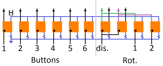
As can be seen from the wiring diagram above the 6 OCs on the left side controls the 6 buttons and the 4 on the right hand side controls the rotary knob. We input a digital high/low value on the bottom which signals a certain output on top, to the coffee machine. The resistors are 270Ω, common ground is from the Raspberry Pi and H is common high from the CoffeePi (see the blue markings in the wiring photos in The CoffeePi (Part 1 of 2); the original annotated image is gone).
When the dis. pin is set high the rotary knob works in its normal manual way. When we set it low, the black inputs (generated from manual rotation of the knob) are _dis_abled and we can instead send our own pulses using Rot.1 & 2.
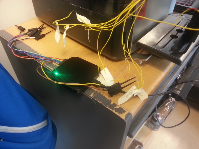
For reference, the wiring looks like this in real life
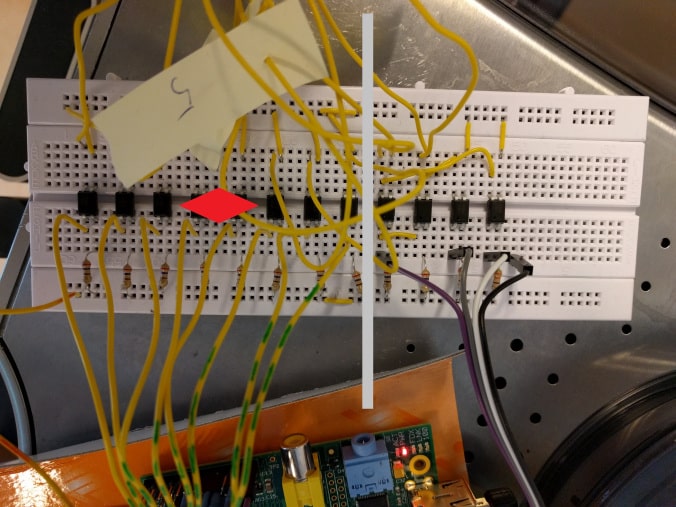
As always, the real projects end up being messier than on paper but both images have the same layout: 6 OCs for the buttons on the left and 4 OCs for the rotary knob on the right.
Adding the Nabto framework
Since our platform is the Raspberry Pi (Linux) I suggest checking out Raspberry Pi 3 IoT, perfect for Nabto for instructions on how to get the uNabto software up and running in no time. After that please check out The SunPi control center to get an idea of how we get a browser to communicate with our uNabto software. For now we only need to worry about unabto_application.c in the src folder.
Making the full menu available
In The CoffeePi (Part 1 of 2) we were only able to progammaticrally push a button after we manually turned the rotary knob to the correct position. Since we now have an understanding of how the rotary knob creates pulses we can now make the full menu available. This is done in the following few steps (code snippets taken directly from unabto_application.c)
Disable manual control
// Shut off manual control
digitalWrite(11, LOW);
delay(wait_msec);
As well as disabling manual control from the rotary knob, the two pins are pulled low such that we always have the same initial setting.
Get a starting point
Since we have 9 available items on our menu we begin by going 8 steps to the left
// Go all the way to the left
for (i = 0; i < 5; i++){

    digitalWrite(13, HIGH);
    delay(wait_msec);
    digitalWrite(14, HIGH);
    delay(wait_msec);
    digitalWrite(13, LOW);
    delay(wait_msec);
    digitalWrite(14, LOW);

    delay(wait_msec);
}
This is done to ensure that we always have the same starting point when getting to the next step.
Selecting desired product
All our pins are now low and it is finally time to go to the desired product. Each item has a certain number associated with them (from the radio buttons) which directly corresponds to how many steps we need to move to the right.
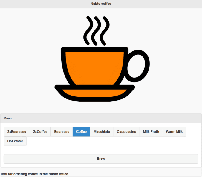
The most popular choice is, of course, Coffee and thus it is pre checked when accessing the CoffeePi online. This button has a value, or id, of 3 so when we click Brew the number/id is send using a Nabto request.
// Go id amount of steps to the right to the desired item
for (i = 0; i < id; i++){
    // If odd
    if (i % 2 != 0){
        digitalWrite(14, LOW);
        delay(wait_msec);
        digitalWrite(13, LOW);
    }
    else{
        digitalWrite(14, HIGH);
        delay(wait_msec);
        digitalWrite(13, HIGH);
    }
    delay(wait_msec);
}
After that bit we should now be at the desired item, and we can now emulate a button press
// Push button
digitalWrite(10, LOW);
digitalWrite(10, HIGH);
delay(100); // 0.1 sec
digitalWrite(10, LOW);
The item should now be brewing!
Clean up
While our lovely hot beverage is being brewed we send a few extra commands. First, we ensure that the two pins controlling the pulses are being set low again and finally, we turn on manual control of the rotary knob again.
// Set the steppers to low
digitalWrite(13, LOW);
digitalWrite(14, LOW);

// Turn on manual control
digitalWrite(11, HIGH);
Remarks
Since we started using a synchronous event handler, the Nabto framework expects to get a response in just 10 msec – so we need to run all this pin switching in a separate thread. The thread is set to being detachable, such that it will self terminate when all code inside the thread has been executed. Please see the appropriate code. In a later post, we will show how to use an asynchronous approach instead and save this separate thread.
From London with love
What better way to demonstrate the true IoT this coffee machine has now become by ordering a cup of coffee from London and then seeing it being brewed in Denmark a few seconds later?
Notice how my colleague in London is laughing through the process!
If you suddenly got the urge to create your own IoT device using Nabto feel free to check out nabto.com and sign up for a developer account at the Nabto Cloud Console. You can for free create and manage 10 devices. This is also where you can find the SDKs and other Nabto software!
The full code for the CoffeePi can be found right here.