
When I asked if I could hack the 1300$ (8800 dkk) coffee machine at the Nabto headquarters the responses varied from “no way” to “I’ll give it 30 % chance of success”. Eventually they surrendered to my request, so let’s see if it all worked out!
Since this project was rather substantial, the coffee machine saga will be split in two (possibly three later on) parts.
In this part we will be dealing with
- Disassembling the coffee machine and finding points of interest
- Figure out the what is needed to control the buttons
- Brew an actual cop of coffee using SSH.
Part 2 will deal with
- Figure out how to wire up and emulate the rotary knob
- Adding the Nabto framework
- Making the full menu available
- Order a cup of coffee in London, get it seconds later in Denmark
Disassembling the coffee machine
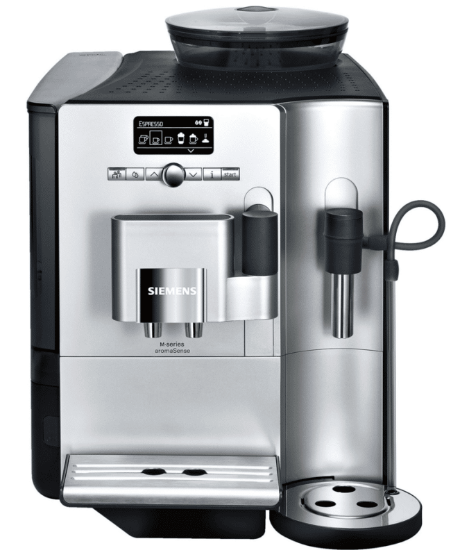
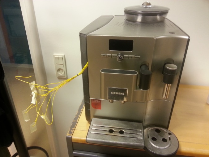
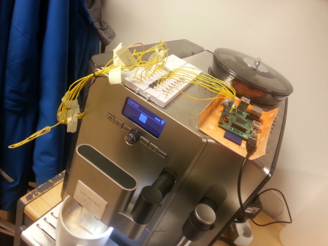
The starting point was the Siemens EQ 7 (TE712201RW) coffee machine, as seen in its standard form in the image above.
First of I had to decide whether to try and access the three pin service port or to rip the machine apart and make some proper hacking. Since I found no information about this service port online I decided on the latter (plus it sounded like a lot more fun).
Machines like these are built with as few screws as possible and thus all side panels are hold in place by small plastic pins. Furthermore the machine is made such that to get to the main board you have to remove the back panel, then the side panels and finally the front panel. In total, dismantling the coffee machine was not easy but I did it MANY times in the process because of broken soldering or crushed wires.
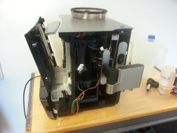
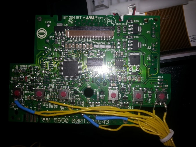
With the front finally of it was time to have a look at the main board.
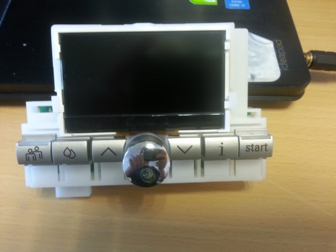
We see 6 buttons and a rotary knob in the middle. Now we just need to check out what is underneath.
Controlling the buttons
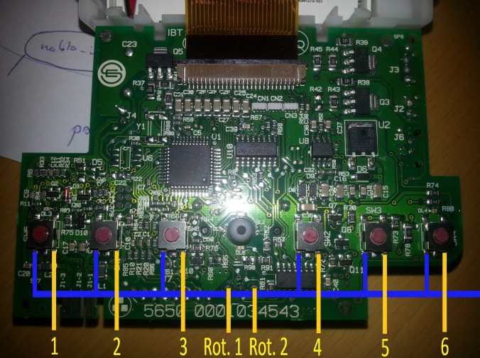
Using a multimeter I began by figuring out any common connections indicated by the blue lines in the above image.
When one of the buttons are pushed a connection is made between the blue and yellow side of the button. We want to be able to create artificial button pushes and thus we need to solder on wires at every yellow line in the above picture and a common blue wire.
We can now imitate a button push by simply shortening common with any of the buttons. To control this programmatically I went with optocouplers, specifically Fairchild 817 chosen because it has a high CTR min. meaning that we can directly activate them using the 3.3V digital pins from a Raspberry Pi, as seen below.
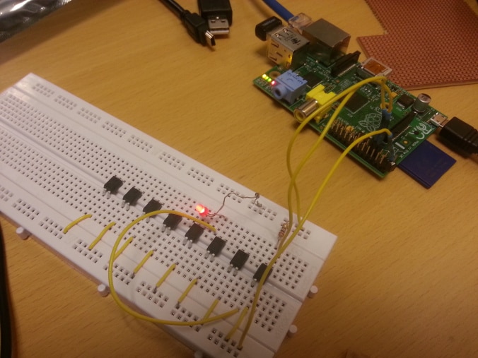
I chose optocouplers since they are basically “light relays” as my colleague said.
This turned out to be a good choice since the logic of the coffee machine runs at 5V and the Raspberry digital pins run at 3.3V, as mentioned earlier.
All that is left is then to hook up the main board again and follow the on screen instructions:
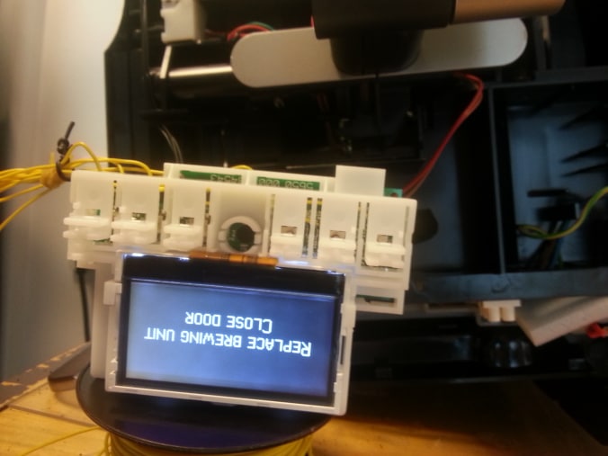
After “closing the door” we need to mark the wires such that we know what they do.
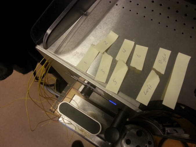
I simply shorted each wire with the common wire (see above) to figure out the function of each wire.
As seen above the wires are now coming out of the coffee machine in a nice little bundle. We now simply need to wire up alle the optocouplers to the raspberry pi and when that is done connect everything together.
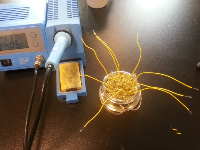
Since I did not have any connectors lying around I had to create some using a bit of soldering.
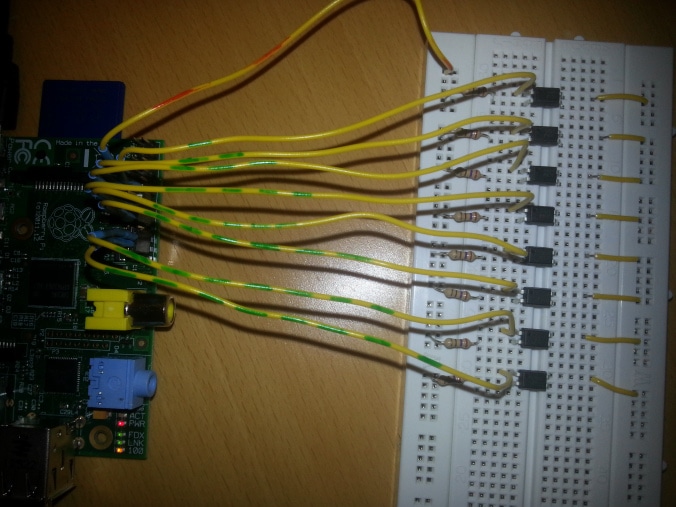
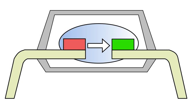
To avoid damaging the optocouplers (and RPi) I inserted a 270Ω resistor alongside each. The “red” wire above is common ground and the numbered “green” wires are the wires we can digitally set high/low. When we set an optocoupler high it means that power is allowed to flow through on the right hand side in the image above, i.e. a button on the coffee machine is pushed.
Have a cuppa
We can now finally wire everything together such that we can click any of the six buttons by issuing a simple command over SSH:
gpio write 10 1
gpio write 10 0
This basically emitates pushing the button in (first line) and then releasing it again (second line).
So far we still have to manually scroll to the desired item in the menu, but when we are there we can programmatically push the button, as seen below:
Great success!
Issues
As mentioned, we still have to manually scroll to the desired menu item before we can programmatically push a button.
The next part will be dealing with this problem as well as a few others:
- Figure out how to wire up and emulate the rotary knob
- Adding the Nabto framework
- Making the full menu available
- Order a cup of coffee in London, get it seconds later in Denmark