
Ever since I first build my solar powered Raspberry Pi system, called the SunPi, I wanted to be able to remote control it.
More specifically, in the summertime, when the sun shines heavily the battery would be filled within an hour after sunrise. The rest of the day, the charge controller would simply waste/curtail excess energy by dumping it as heat. Instead of doing that I wanted to use this energy for something. Specifically I wanted to be able to remote control a relay such that I could activate whatever device I had lying around.
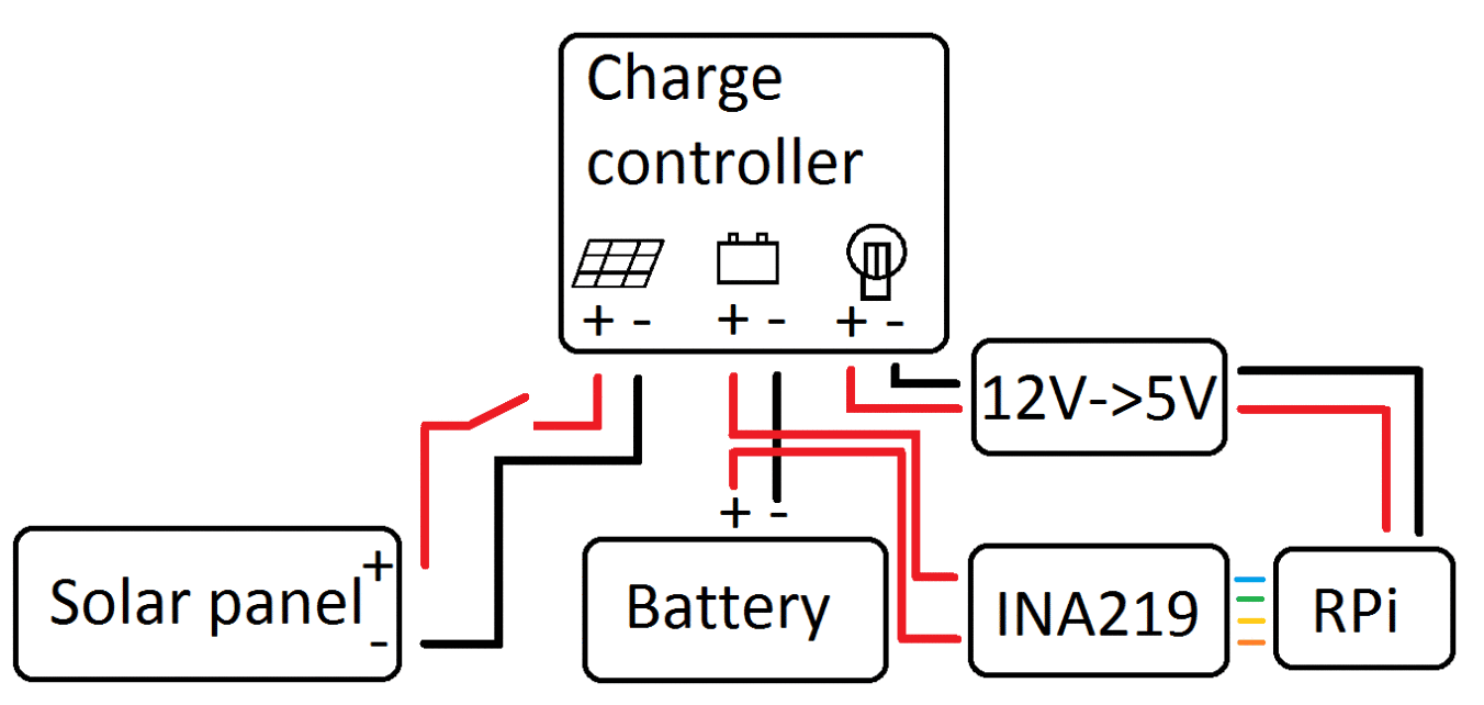
To determine whether or not to activate the relay I had to be able to read the voltage level which is equivalent to how filled the battery is. I did this using a INA219 current sensor, some Python and plotted it here. But I really wanted to have everything on a single page such that I could quickly determine whether or not to activate the relay. I wanted to be able to access this control center from anywhere and in a secure way. With Nabto I found the solution
How Nabto works
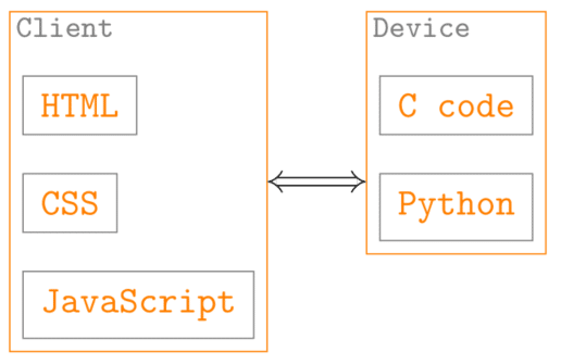
As seen in the above figure the client side (e.g. the device you are reading this on) has HTML, CSS and JavaScript running when you visit the SunPi control center. Altering a slider in the HTML calls a JavaScript function which in turn sends a Nabto request to the device side of things. In this case the device is a Raspberry Pi running some compiled C code. For our power and voltage readings (more below) a Python script is called from within the C code. That is basically all there is to the framework.
To get a better feel of how to add functionality I will walk through
- Controlling a GPIO pin
- Retrieving data
Note that these examples build on the default html_dd (Client side) and this RPi demo (Device side).
Controlling a GPIO pin
HTML
We start by creating a slider with a unique id (rgb-r in this case) containing the OFF and ON options.
<li>
  <h2>Red</h2>
  <div class="ui-li-aside">
    <select id="rgb-r" data-role="slider">
      <option value="off">OFF</option>
      <option value="on">ON</option>
    </select>
<li>>
JavaScript
When the slider with the rgb-r id is toggled, the accompanying JavaScript-script is activated.
$("#rgb-r").change(function(){
  var state = $(this).val() === "off"?0:1;
  jNabto.request("light_write.json?light_id=1&light_on="+state, setLight_r);
});
Where the setLight_r function shifts the actual slider. What is perhaps more interesting is the jNabto.request part. The jNabto requests are defined in the unabto_queries.xml file and the light_write.json used above look like this
<query name="light_write.json" description="Turn light on and off" id="1">
  <request>
    <parameter name="light_id" type="uint8"/>
    <parameter name="light_on" type="uint8"/>
  </request>
  <response format="json">
    <parameter name="light_state" type="uint8"/>
  </response>
</query>
As seen, the request sends the two light_id and light_on variables containing information about which pin/light we are dealing with and which state (light_on) we want it in. After this, we expect to receive a json format response, specifically the light_state the pin has been set to. We notice that the query id is 1.
C code
On the device side we arrive at case 1 (in unabto_application.c) since the light_write.json has id = 1.
case 1: {
    uint8_t light_id;
    uint8_t light_on;
    uint8_t light_state;

    // Read parameters in request
    if (!buffer_read_uint8(read_buffer, &light_id)) {
        NABTO_LOG_ERROR(("Can't read light_id, the buffer is too small"));
        return AER_REQ_TOO_SMALL;
    }
    if (!buffer_read_uint8(read_buffer, &light_on)) {
        NABTO_LOG_ERROR(("Can't read light_state, the buffer is too small"));
        return AER_REQ_TOO_SMALL;
    }

    // Set light according to request
    light_state = setLight(light_id, light_on);

    // Write back pin state
    if (!buffer_write_uint8(write_buffer, light_state)) {
        return AER_REQ_RSP_TOO_LARGE;
    }
    return AER_REQ_RESPONSE_READY;
}
Most of this is for error logging, we only need to focus on the setLight function and how we plan on sending a message back to the client side afterwards. The setLight function looks like this
// Set GPIO pin and return state,
uint8_t setLight(uint8_t id, uint8_t onOff) {
    theLight[id] = onOff;

    NABTO_LOG_INFO(("Nabto: %s turned %s!n", pin_name[id], on_off[theLight[id]]));

#ifdef __arm__
    /* Toggle GPIO pins on Raspberry Pi	*/
    //Change pin output according to id and theLight state

    if (theLight[id]){
        //Activate pin
        digitalWrite(pin_id[id], LOW);
    }
    else if(theLight[id]==0){
        digitalWrite(pin_id[id], HIGH);
    }
#endif

    return theLight[id];
}
Where we toggle the chosen pin on or off depending on the light_on variable passed from the client.
When we sucessfully set the actual pin we write back the pin state to the client using the buffer_write_uint_8 command. And that is bascially all you need to control a GPIO pin on the Raspberry Pi using the Nabto framework.
Retrieving data
HTML
The HTML code for retrieving data is basically just a button which signals the JavaScript to do a certain task, in this case we are dealing with id=”ina_update” (remember, we are using a INA219 current sensor).
<li>
  <input type="button" id="ina_update" data-icon="refresh" value="Read Voltage and Power"/>
</li>
JavaScript
The accompanying JavaScript function look like this
$("#ina_update").click(function() {
  queryINA219($(this));
});
where
function queryINA219(input) {
  jNabto.request("ina_data.json?", function(err, data) {
    if (!err) {
      temp_power = data.power_w/10000

      // Check if negative
      if (temp_power > 100)
      {
        temp_power = temp_power - 200
      }

      input.val("Voltage: " + (data.voltage_v/10000).toFixed(2) + "V, Power: " + temp_power.toFixed(2) + "W").button("refresh");
    }
  });
}
contain the ina_data.json jNabto request. Again we check the unabto_queries.xml file and make sure that
<query name="ina_data.json" description="Read voltage and power status" id="3">
  <request>
  </request>
  <response format="json">
    <parameter name="voltage_v" type="uint32"/>
    <parameter name="power_w" type="uint32"/>
  </response>
</query>
the ina_data.json query id is 3.
C code
The request is sent to the device side where we end up in case 3 because the ina_data.json request has id = 3.
case 3: {
    // Get voltage from INA219
    getINA219_data(&voltage, &power);

    NABTO_LOG_INFO(("Nabto: Read voltage=%f and power=%fn", voltage, power));

    // Write back data
    if (!buffer_write_uint32(write_buffer, voltage*10000))
    {
        return AER_REQ_RSP_TOO_LARGE;
    }

    // Prepare for negative numbers. This will be converted back in the html_dd app.js file
    if (power<0)
    {
        power = power + 200;
    }

    // Write back data
    if (!buffer_write_uint32(write_buffer, power*10000))
    {
        return AER_REQ_RSP_TOO_LARGE;
    }
    return AER_REQ_RESPONSE_READY;
}
As seen above, the power data needs special preparation since we are writing uint32 (unsigned, i.e. numbers are always positive). When the battery charges the power is defined to be positive and when it discharges it is of course negative. Since my solar panel has a maximum rated power of 100W (which it never reaches) and my maximum power consumption is 10W at any given time, I simply add 200 to the power measurement. I made sure to undo this addition in the accompanying JavaScript as seen above (// Check if negative). Finally we take a look at the getINA219_data function,
// Get INA219 data
void getINA219_data(float* voltage, float* power){

    FILE *fp;
    char path[1035];
    /* Open the command for reading. */
    fp = popen("sudo python path/to/ina219_python_c.py", "r");

    if (fp == NULL) {
        NABTO_LOG_INFO(("Failed to run Python scriptn"));
        exit(1);
    }
    /* Read the output a line at a time - output it. */
    int k = 0;
    while (fgets(path, sizeof(path)-1, fp) != NULL) {
        k = k + 1;
        if (k==1){
            *voltage = atof(path);
        }
        else if(k==2){
            *power = atof(path);
        }
    }
    /* close */
    pclose(fp);
}
The function calls a Python script which print out two lines of data. The lines contain the voltage and the power flowing in or out of the SunPi battery, respectively. The data is then sent back to the client side using the buffer_write_uint32t command as seen above. These are the building stones for how to write a simple Nabto application. After expanding on this a bit I finally had my control center.
The SunPi control center
Thus I can now simply access the Nabto SunPi control center (just click on guest to try it out. NOTE: no longer available) and then check the voltage. The battery is full when the voltage is above ~13V. If that is the case I can activate the relay or use the extra power for an RGB LED.
The full code is available on Github.
That’s all!