Important notice: This post is about the legacy Nabto 4/Micro platform which has been superseded by the Nabto 5/Edge platform. Nabto Edge officially supports ESP32 – and there is a new tutorial for How to Make a Low-Cost ESP32-based Remote-accessible Camera using ESP32-CAM or ESP32-EYE Board available.
In our former blog post ‘RTSP P2P streaming through Nabto‘, where we talked about how to create an app that enabled remote accesses to an RTSP camera, we used a large Linux-based camera. Later on, we have received many requests on how to do the same type of integration to a ‘low-cost’ WI-FI module-based camera – and that is exactly what we are going to cover in this blog post.
Example of how to use the app to remote control your ESP-camera when you have completed this guide.
In this blog post you will learn:
- How to make a small low-cost surveillance camera – including app and device source
- How to use an ESP32 + Omnivision-based camera module to make it remote accessible
Introduction
Creating a locally accessible camera application with the ESP32 is something that has already been done. But why do you need a camera that you only can access on your local network? You can just go look at the thing that the camera is capturing instead of looking at it on your computer or app (unless you have a very big house). The hard part is to make it remotely accessible and to do this securely.
Fortunately, this is exactly what our technology does. With Nabto you can create a remote connection from a client (smartphone or PC) directly to an IoT device. This remote connection uses P2P technology (the same technology as used in Skype, TeamViewer, etc.), has high security (we use state-of-the-art authentication, integrity check and encryption algorithms) and which is made for all embedded devices. Hopefully, with this explanation, you will understand the schematics of the Nabto platform below a lot better.
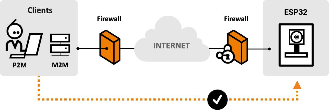
The Nabto Platform
Motivation – why do I need this?
Many of our customers have asked us to showcase small, embedded-style cameras. If you are not one of them, maybe you are trying to figure out why this is important.
Simple and secure standard surveillance camera
A simple use case could be that you want to make a standard low-cost, uncomplicated (and secure) surveillance camera. Standard surveillance cameras are often shipped with tons of software which must then be supported with updates, security fixes, etc. A stripped down environment without a desktop/server scale operating system and running services is hence inherently more secure with its much smaller attack surface. But if that is not enough, low cost and small size should convince you.
Remote video feed in other application
A lot of our customers make video surveillance cameras as standalone applications, i.e. you install it and it streams video to your phone whenever you need to see what is happening on the remote end. However, we see more and more projects where streaming video as part of another application. For example, pet feeders with a video stream, doorbells with both audio and video capabilities, 3-D printers you can monitor, etc.
The technical part
Research
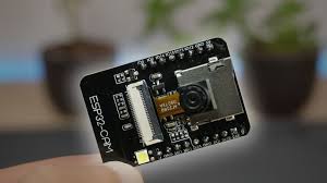
ESP32-CAM from Ai Tinker
So, we did some research of the market and found that Seedstudio’s ESP32 CAM was a great place to start and which was probably was one of the first ESP32-based cameras out there. It is low cost and has everything on board that we needed including a nice demo. Later we found out that Espressif, the maker of ESP32, has created a module too called ESP-EYE.
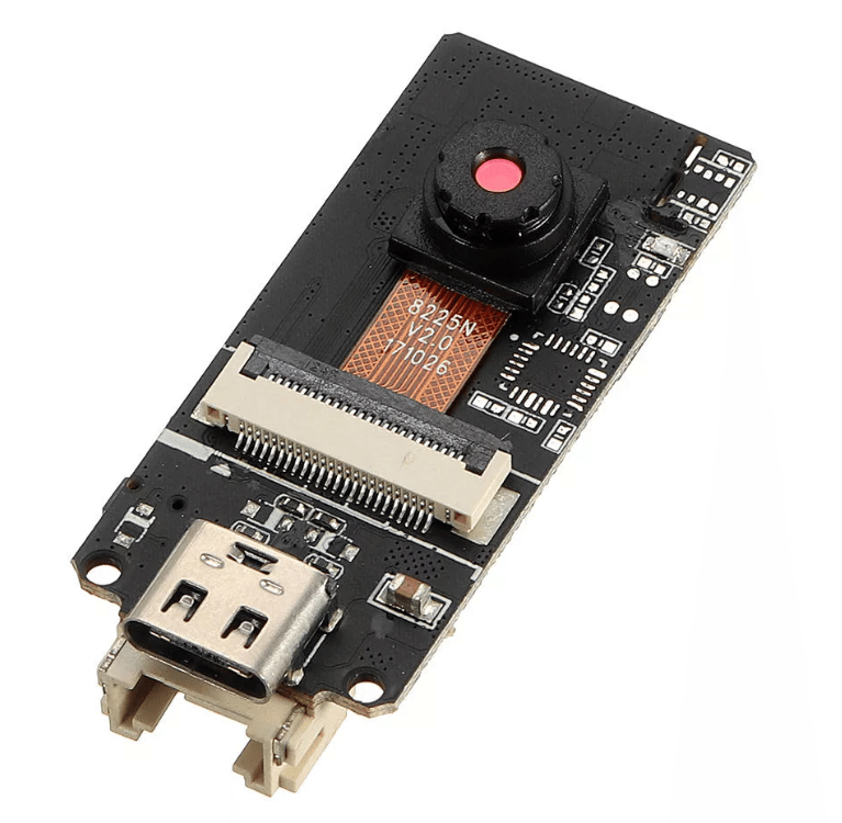
M5Stack ESP32 Cam
We started out with development on the M5Stack ESP32 Cam. It doesn’t have the extra external RAM but instead, it had a USB to the ESP32 UART on board which made it much easier to program (you don’t have to fiddle manually with GPIO0, etc. to get into flash-programming mode)
The problem with the M5Stack is that it lacks the external memory and when you need to stream a lot of data and do it fast, you need to keep a buffer of unacknowledged packets flowing from the camera to the app, ready to resend if the packets are lost in transit. Also, you need to buffer the framebuffer from the camera. This could, of course, be optimized so everything uses the same buffer, but this would go against the separation of concerns principle and also make the integration much harder.
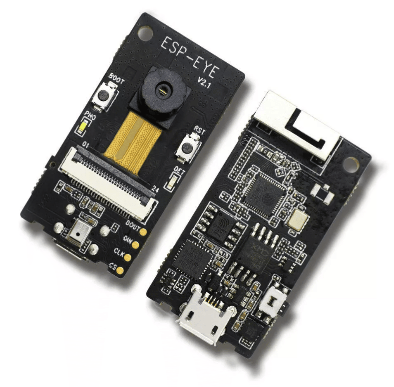
ESP-EYE from Espressif
As mentioned above, we found out that the maker of the ESP32 chip had created their own camera module. It was a little more expensive but the good thing was it came with USB to UART on module for easy programming.
Design
The next decision was how to do the technical software design.
Direct streaming
One way was to create a Nabto P2P stream directly from the app connecting to the camera and push the stream directly onto a canvas of some kind. This would require lots of coding on the app side but would probably be super-fast.
P2P Tunnel MJPEG via HTTP
Instead, we chose to test if we could reuse the app from an old demo using an RPI as a remote camera. The overall design is very similar to SSH tunnel techniques. The demo will establish a TCP server port on the app side that is connected to a tunnel server on the camera side. Once a client (a webview) connects to the server port on the app side, the tunnel server on the camera side would create a TCP connection to the web server.
On both sides, all received data will be forwarded to the other side. This makes it seem to the client like the web server on the camera side is running on the app side, since a get request will be forwarded to the camera side and the camera response will be forwarded to the app side. This way you can use a standard app webview to connect to the web server on the camera (using the tunnel to remotely forward the data).
If this seems like incomprehensible gibberish to you, try do a Google search on “SSH tunnels”, it’s the same principle, just using Nabto streams instead of SSH streams.
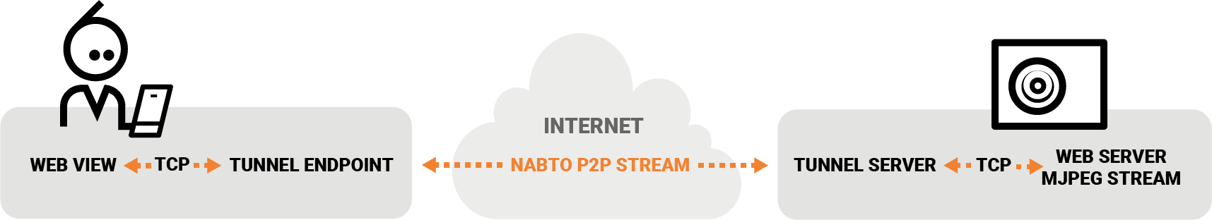
Overview of the tunnel setup in the camera demo
If you haven’t set up the esp-idf development environment yet, you should follow the guide here (WARNING – INSTALL v4.0!!):
Start out by cloning the project (REMEMBER the ‘–recursive’ flag):
$ git clone --recursive https://github.com/nabto/nabto-esp32cam.git
Cloning into 'nabto-esp32cam'...
Configure the project as described in the following. You need to supply your WiFi SSID and password.
You also need to fetch a Device ID and a Device Key for free from Nabto cloud console (Nabto’s self-service SaaS portal). Both need to be written into the “Camera configuration”.
$ cd nabto-esp32cam
$ make menuconfig
Chose the “Camera configuration” menu:
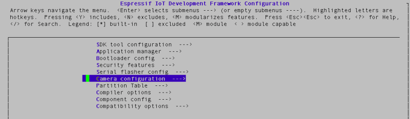
Configure the WI-FI SSID and Password. Configure the ID and KEY used for remote access.
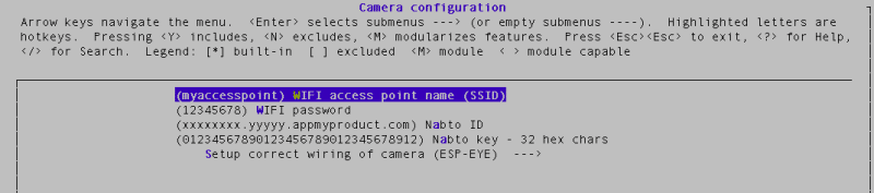
If you have an ESP-EYE board nothing else needs to be set up, but if you have an “ESP32 Cam” from Ai Tinker, you need to configure this too (also in the “Camera configuration” menu). Choose “Setup correct wiring of camera” in the menu config.
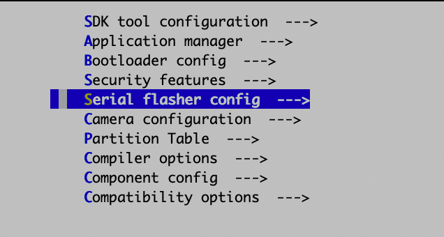
Adjust the serial device on your workstation used to flash (and monitor) the device:
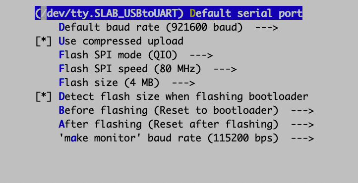
Note that on macOS, the serial port may require a few steps to work if you have not set it up before. The official docs describe how to identify the port. See this discussion if the port does not appear: Basically you must first install a driver and then allow it to be loaded by the OS.
Once configured, make the project and flash it (btw. for some reason we get *** No rule to make target ‘esp32/gpio_periph.o’ … if you do.. just do it again and it will disappear)
$ make -j 4

...

$ make flash
If you ‘monitor’ the device
$ make monitor
...

I (1534) tcpip_adapter: sta ip: 192.168.2.147, mask: 255.255.255.0, gw: 192.168.2.1
00:00:01:457 main.c(134) connected1!

00:00:01:457 main.c(386) connected!

00:00:01:461 main.c(392) IP Address:  192.168.2.147
00:00:01:465 main.c(393) Subnet mask: 255.255.255.0
00:00:01:470 main.c(394) Gateway:     192.168.2.1
00:00:01:475 unabto_application.c(59) In demo_init
00:00:01:479 unabto_application.c(78) Before fp_mem_init
00:00:01:610 unabto_application.c(81) Before acl_ae_init
00:00:01:611 unabto_common_main.c(110) Device id: 'jicnkjqs.ev9dbf.trial.nabto.net'
00:00:01:612 unabto_common_main.c(111) Program Release 4.4.0-alpha.0
00:00:01:618 network_adapter.c(140) Socket opened: port=5570
00:00:01:624 network_adapter.c(140) Socket opened: port=49153
00:00:01:629 unabto_stream_event.c(235) sizeof(stream__)=328
00:00:01:634 unabto_context.c(55) SECURE ATTACH: 1, DATA: 1
00:00:01:639 unabto_context.c(63) NONCE_SIZE: 32, CLEAR_TEXT: 0
00:00:01:646 unabto_common_main.c(183) Nabto was successfully initialized
00:00:01:652 unabto_context.c(55) SECURE ATTACH: 1, DATA: 1
00:00:01:657 unabto_context.c(63) NONCE_SIZE: 32, CLEAR_TEXT: 0
00:00:01:664 network_adapter.c(140) Socket opened: port=49154
00:00:01:668 unabto_attach.c(770) State change from IDLE to WAIT_DNS
00:00:01:674 unabto_attach.c(771) Resolving DNS for jicnkjqs.ev9dbf.trial.nabto.net
00:00:01:785 unabto_attach.c(790) Resolved DNS for jicnkjqs.ev9dbf.trial.nabto.net to:
00:00:01:786 unabto_attach.c(796)   Controller ip: 34.232.129.33
00:00:01:788 unabto_attach.c(802) State change from WAIT_DNS to WAIT_BS
00:00:01:998 unabto_attach.c(480) State change from WAIT_BS to WAIT_GSP
00:00:01:999 unabto_attach.c(481) GSP address: 34.194.195.231:5565
00:00:02:005 unabto_attach.c(270) ########    U_INVITE with LARGE nonce sent, version: - URL: -
00:00:02:308 unabto_attach.c(563) State change from WAIT_GSP to ATTACHED
It’s important that the Nabto state changes to ATTACHED which means that the device has registered with the Nabto cloud and is ready to receive incoming remote P2P connection requests.
Now download the appropriate app for your phone:
Android: https://play.google.com/store/apps/details?id=com.appmyproduct.video
iOS: https://itunes.apple.com/lc/app/appmyproduct-video-client/id1276975254
First, for pairing the App and the device, connect your phone to the same WI-FI as you configured the camera module to use. Then start the app.
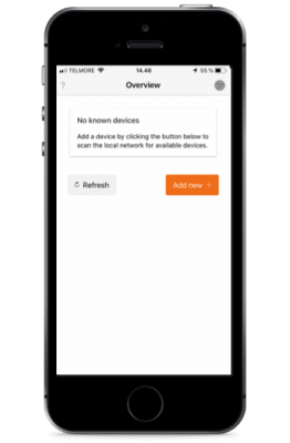
Click the “Add new +” button. The app should hopefully now discover the camera on the local network.
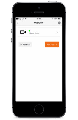
You can connect to the camera on the local area network (not a big deal, you could this as well without Nabto). However, more importantly, you should now be able to disable WI-FI on your mobile device and access the camera using your cellular data (or connect to the internet via another WI-FI). If it would be of help, you can see the process in the video below.