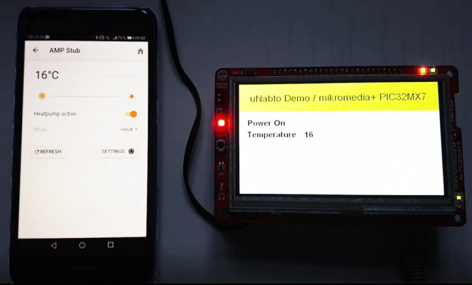
You can say a lot about Modbus, like “old and primitive” but it’s definitely also a protocol that is very widely used and common in many products today. However, it is worth remembering that primitive is sometimes good, especially when you are interfacing systems. The modbus slave (blue box) is a Digital/Analog converter that can sample simple analog (like PTC sensor) and digital sensor input and store this in Modbus registers. The RPI gateway can readout these Modbus registers so clients can read it via Internet
Therefore it should not come as a big surprise that we have received many requests at Nabto on how to integrate to Modbus-based devices. Apart from many other Modbus apps, our app makes it possible to remote control with P2P wherever you are.
Normally, when you say Modbus you also say RS485, because Modbus is a protocol on top of a serial data connection and RS485 is able to establish serial communication over relatively long distances (1200m) with an okay speed (up to 10Mbit/s) which in most Modbus use-cases is more than enough, and all this only using a set of twisted shielded wires.
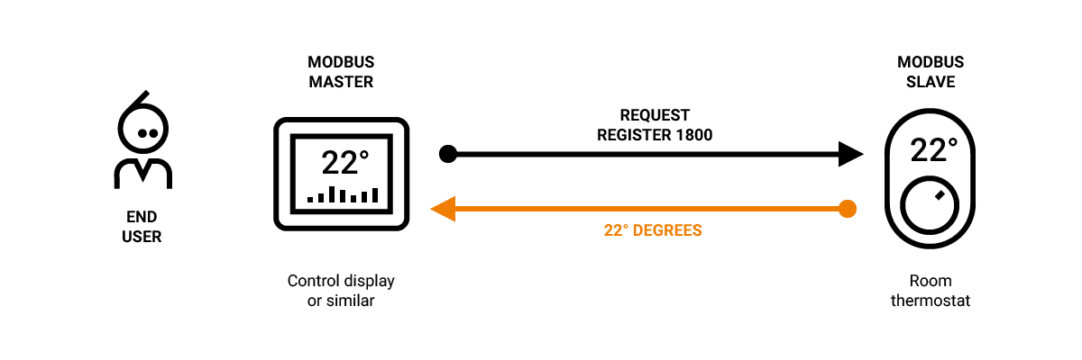
Also, Modbus is a request/response-based protocol perfect for integration with Nabto’s request/response protocol. For example, let’s imagine a Modbus thermostat controller server device exists (which in Modbus terminology is a slave device). This controller contains a certain register, let’s say 1800, which represents the current measured temperature. End users would be interested in knowing the current temperature and would thus request the contents of register 1800. Some kind of Modbus client (in Modbus terminology a master) would request this register 1800 and the server device would answer with the current temperature measurement and the client would show this temperature on a screen, etc.
Choosing a Modbus gateway for the demo
So with a lot of devices out there already using RS485+Modbus and a lot of end users out there with Internet-connected smartphones, it’s not a surprise that a lot of customers ask about how to create apps that remotely connects to RS485 based Modbus and requests data that is then presented in the app. Something like what is presented in this schematic drawing:
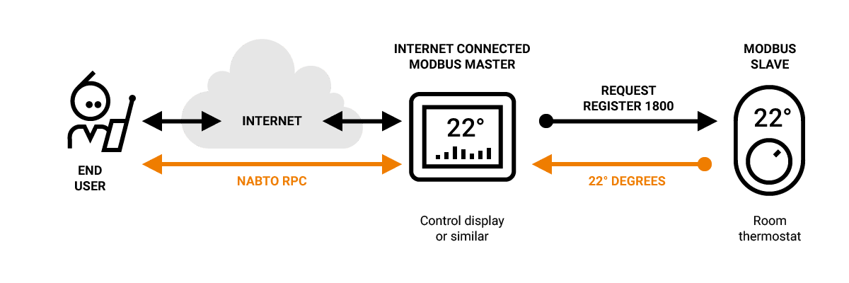
Fortunately, this is not very hard to accomplish using the Nabto platform. Nabto RPC can be used for transmitting the request/response and the only thing needed is to create a Nabto RPC to Modbus translation.
One of the requirements we had for the demo would be able to configure the app to be able to access specific Modbus slaves. This, of course, requires some kind of configuration file that tells the app what registers to get from the slave and how to present them. Since the app is to be published in the Apple App Store, little alteration can be done (unless you make a configurator inside the app) so instead, it was chosen that the device (the Modbus gateway) should be able to provide a simple JSON-based configuration to the app once the app was connected to the device. We don’t think this is a road to travel down in a real-life production setup, but for testing, it should be easy for the tester to rewrite the configuration to match the registers of the device needed to be interfaced.
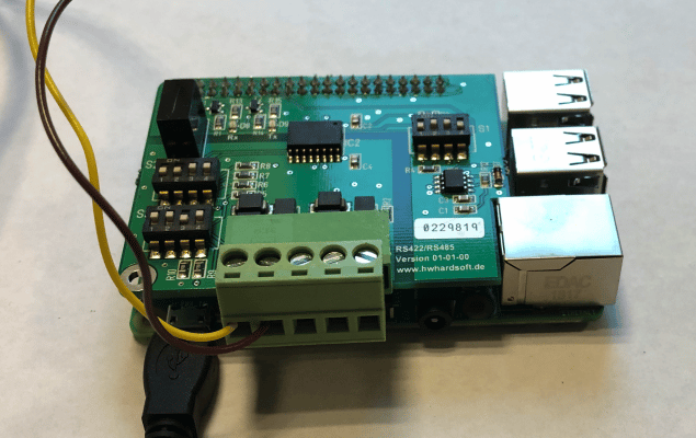
The hardware chosen for the test prototype was an RPI setup with an RS485/RS422 HAT. Other cheaper/simpler options are out there, but based on experience, RS485 termination (which can be configured via DIP switches) and other compatibility issues can sometimes be quite “a stone in the shoe”, so we chose to go forward with this board, and we were right. We also had a cheap USB to RS485 lying around and once we had the HAT board up and running, we thought that just for the heck of it, we should try out the USB option. We can tell you it was time-consuming to get it to work with DIY resistor termination, etc. (only go there if you know what you are doing and regard hours of tinkering as fun).
This is how the RPI and RS485 HAT looks like when put together:
We need to note that the demo can probably run on any (Unix) type of system which allows you to access a serial line via a file descriptor (i.e. normally present in /dev/ttyXX). Some rough smoke testing has been done on a Mac OS computer with a USB to RS485 connector running the same compiled software that is presented here for the RPI. Also a stub (based on libmodbus) is located in the “modbus_slave_stub” directory, which can emulate a Modbus slave using pseudo terminals (i.e. if it is attached to ptyp0, the gateway can open the other end at ttyp0, default present on a BSD type system like MacOS, while Linux systems requires legacy PTY support or magic done with a ‘socat’ program).
Choosing a complete test setup
To make a real demo, a gateway is not enough; we also need to have a Modbus slave that the gateway can do readouts from (initially the gateway can only do readouts, contact us if you need to do updates of registers). Luckily, we had some old Modbus equipment lying around that was acquired for another project. It is a Brainchild IO-DAIO Digital Analog I/O Modbus box. It takes the brain of a child to imagine what this box does (pun intended). It converts analog and digital Input/Output to an RS485 Modbus interface, brilliant for simple testing of our Modbus gateway. From the other project, the box was already hooked up to a temperature sensor and a potentiometer (since in some cases the temp. sensor took too long to react). In a real setup, the Modbus slave could be a solar inverter, ventilation control, heat pump, thermostat, or any other device that can be controlled and managed by Modbus, but the IO-DAIO is simple. We had it lying around and handily, you could carry it home in your briefcase (when you had to work on this demo on the weekend or at night).
So, all put together, you end up something like:
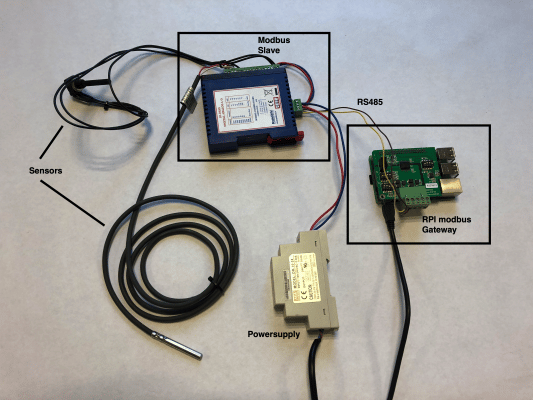
I know, it’s a little messy, so here’s a schematic, it is actually quite simple, what you see in the picture is what is inside the grey box:

Modbus gateway design
It was chosen to keep the design of the gateway simple. The simplest design would be just to keep the gateway transparent, but since some management of applying correct pauses between Modbus transmissions (as pr. Modbus requirements) and also some CRC checking and possible retransmissions had to occur, it was decided that this would happen on the gateway and only the “real” Modbus Data would be managed by the app layer.
Modbus communication:

Instructions – Get to the Choppa!
Well, it is probably best to soon let the wheels hit the pavement (before you get too bored). So, here is what you need to do.
Install the Modbus-HAT on the RPI and connect it to a power source and the Internet (WIFI or Ethernet, this will not be covered here).
Log into the RPI with something like:
$ ssh [email protected]
[email protected]'s password:
…
Last login: Sat Sep 9 09:14:12 2017 from mclappe2.home
pi@rpi:~ $
Then you need to check out the Modbus device code:
pi@rpi-modbus:~ $ git clone --recursive https://github.com/nabto/modbus-demo-gateway
Cloning into 'modbus-demo-gateway'…
…
(NB: remember the –recursive flag)
It should be fairly easy to compile the code running the “build.sh” command (you need to install a compiler and cmake etc., if not present).
The “settings.txt” file defines the RS485 speed and what configuration file to look for concerning register read out. It should look like this:
baudrate=9600
stopbits=1
parity=even
uart=/dev/ttyS0
modbus_configuration=modbus_configuration.json
You need to modify this to your setup.
The “modbus_configuration.json” file defines what registers to fetch via Modbus and how to present them. Best to explain with an example for the Brainchild device:
{"a":1,"r":[{"n":"Temperature","t":"n","r":"0003", "f":"r/10"},
            {"n":"Resitance","t":"n","r":"0005"}
           ]
}
The first ‘”a”:1’ defines which Modbus address to fetch data from.
The “r” variable is a register list consisting of “n” being the name of the register, “t” the type, “r” the register and “f” being the present format. The temperature, for example, is located on address 0x0003 (Modbus address 40004, 0x0003 is the address used in the Modbus data-frame).
The syntax has been created so “tight” since it needs to be able to fit within the max buffer size of the RPC requests (normally around 1400 bytes). A production system should not fetch the configuration from the device, but for this demo, it was chosen so that the app distributed via the App Store and Google Play could be the same for all use cases.
The Modbus demo app can be obtained via Google Play or the App Store, but you can also download, modify and compile it yourself.
Now run the Modbus gateway by running the “run.sh” command. You should create an account on the Nabto cloud console and obtain your own DEVICEID and DEVICEKEY and adjust it in the “run.sh” if you want stable remote access (multiple users using the given device id and key will experience race conditions).
First, the app and device will need to pair (they exchange cryptomatic keys to enable later secure remote access). This looks like: (click ddd new, chose device, confirm pairing, go to device).
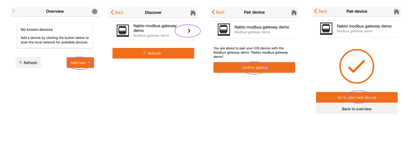
This should get you to a screenshot like this (notice the names of the two registers match the names in the configuration setup above), et voila!:

This screen could be configured to show any type of Modbus register. Currently, the Modbus register type is only numbers. This can easily be altered in the Ionic typescript files. The main fetching of the holding registers happen in the function “readHoldingRegisters”.
readHoldingRegisters(address: number, register: string, words: number, callback: (data: string) => void) {

    var hexAddress = hexconvert.pad(hexconvert.dec2hex(address),2);
    var modbusCmd = hexAddress + var modbusCmd = hexAddress + "03" + register + hexconvert.pad(hexconvert.dec2hex(words),4);

    console.log("Modbus command:" + modbusCmd);

    this.nabtoService.invokeRpc(this.device.id, "modbus_function.json",
                                { "bus":0, "address":hexAddress, "data": modbusCmd}).
      then((state: any) => {

        var tmpStr = state.data.substring(6);

        console.log("data:" + tmpStr);
        callback(tmpStr);

      }).catch(error => {
        console.log("ERROR:"+error);
        this.busyEnd();
        this.handleError(error);
      });

  }
Readers with an understanding of the Modbus protocol will notice that the command is built by the following line:
var modbusCmd = hexAddress + "03" + register + hexconvert.pad(hexconvert.dec2hex(words),4);
I.e. “address of Modbus device” + function code (“03”) + “register to request” + “number of words requested”. This explanation could be helpful. This could easily be adjusted to readout multiple registers (strings or floats etc.). It was the scope of this article to create a simple demo, but if you have any special requirements, please feel free to contact us and we will help you or look into adjusting the demo for your specific set-up.
This is the first public example of how to use Nabto in conjunction with Modbus. The example has been made with simplicity in mind and especially something that is easily testable. Based on the amount of interest, we would gladly publish a follow-up article that addresses what you might want us to help you to accomplish, so please feel free to contact us, either by mail: [email protected] or just comment below.


